
Explain 4 Bit Binary Adder
In Digital Circuits, A Binary Adder-Subtractor is capable of both the addition and subtraction of binary numbers in one circuit itself. The operation is performed depending on the binary value the control signal holds. It is one of the components of the ALU (Arithmetic Logic Unit).
Binary adder circuit / Circuit additionneur binaire
Binary Adder • We implement a binary adder with registers to hold the data and a digital circuit to perform the addition (called a binary adder). • The binary adders is constructed using full adders connected in cascade so that the carry produced by one full adder becomes an input for the next. • Adding two n-bit numbers requires n full.
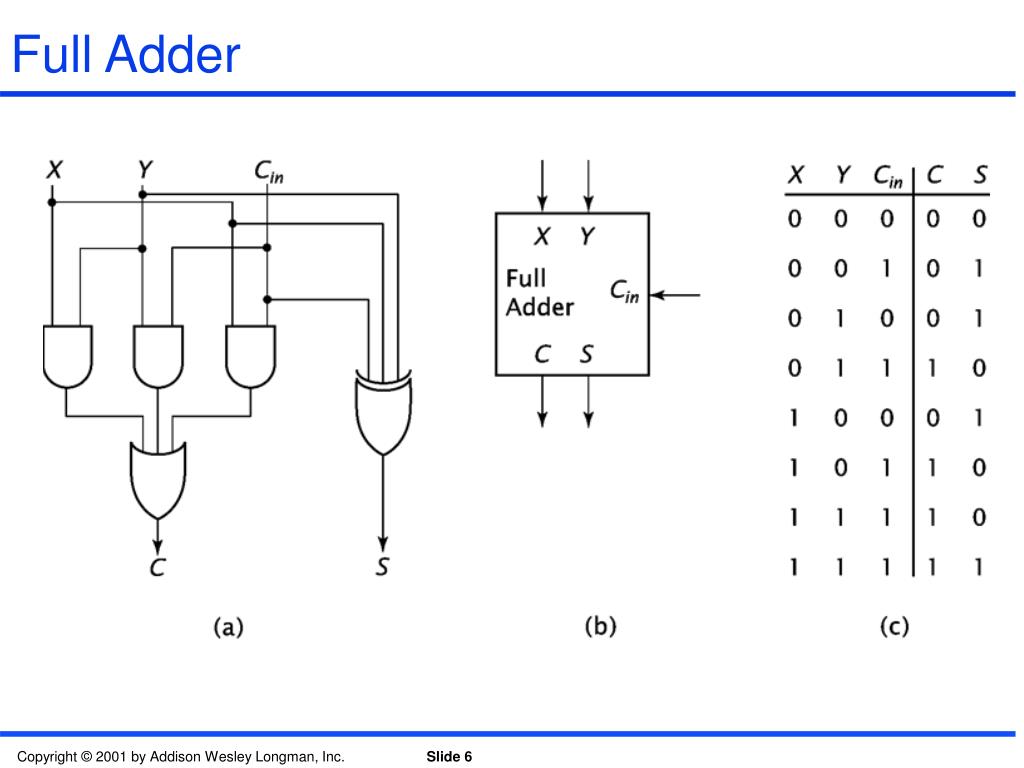
PPT Computer Systems Organization & Architecture Chapter 1 Part 9 Adders and Subtractors
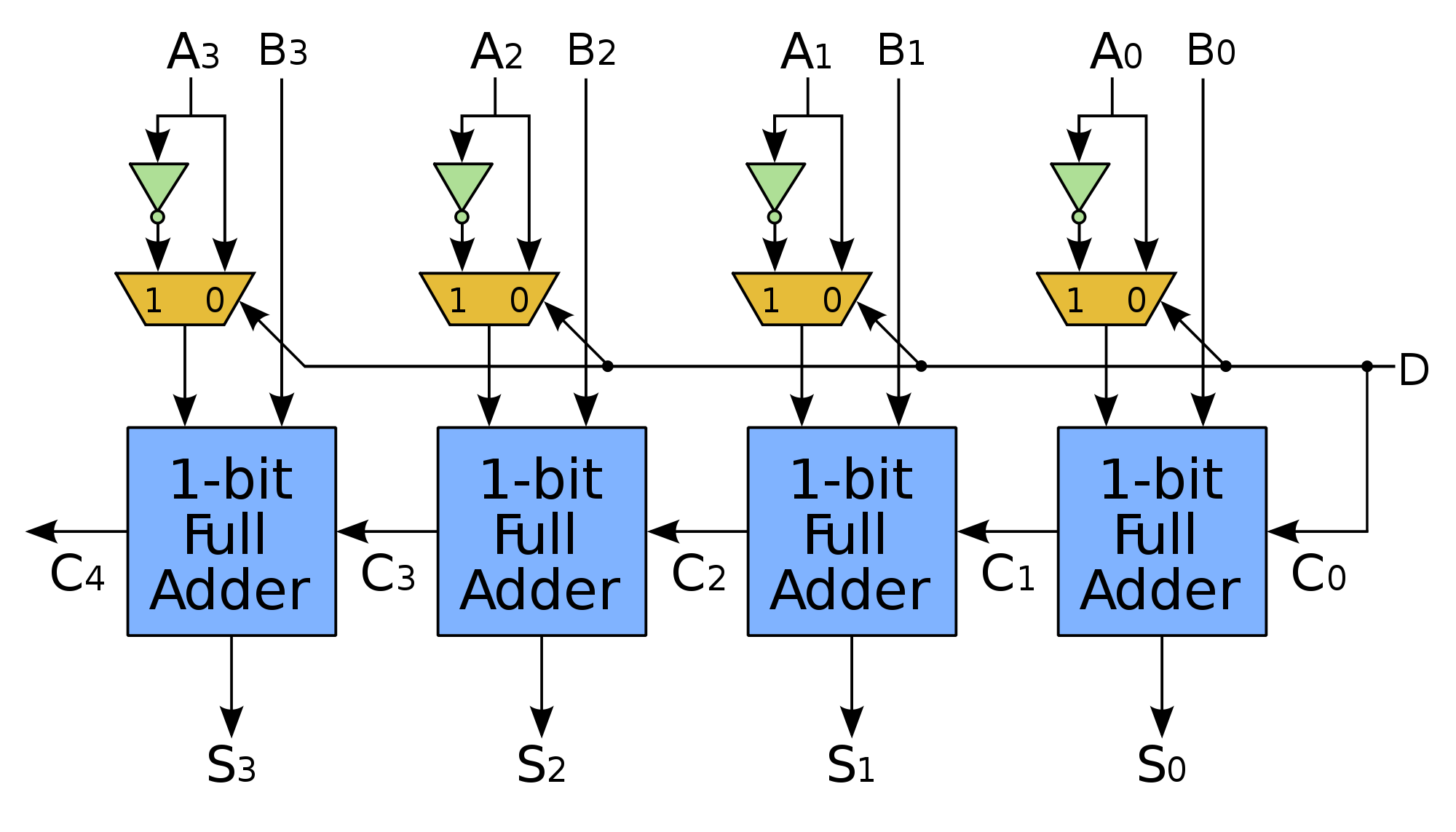
The Ripple Carry Adder (RCA) is the simplest implementation of a binary adder. It is built by cascading multiple full adders (FA), as shown in Fig. 4.5. a k and b k are the two input operands, c k is the carry signal at any stage k > 0, and c 0 is the initial value of the carry signal.

Parallel Binary Adders
Binary adder architectures for cell-based VLSI and their synthesis. R. Zimmermann. Published 1997. Engineering, Computer Science. TLDR. It is found that the ripple-carry, the carry-lookahead, and the proposed carry-increment adders show the best overall performance characteristics for cell-based design. Expand.
4 Bit Binary Adder Circuit Diagram
BCD adder refers to a 4-bit binary adder that can add two 4-bit words of BCD format. The output of the addition is a BCD-format 4-bit output word, which defines the decimal sum of the addend and augend and a carry that is created in case this sum exceeds a decimal value of 9. Therefore, BCD adders can implement decimal addition.

Computer architecture
Principles Of Digital Computing A Binary Adder Vol. Digital Circuits Chapter 16 Principles Of Digital Computing A Binary Adder PDF Version Suppose we wanted to build a device that could add two binary bits together. Such a device is known as a half-adder, and its gate circuit looks like this:
Design of a Serial Binary Adder
The Binary Adder is a logical circuit which is used to perform the addition operation of two binary number of any length. The Binary Adder is formed with the help of the Full-Adder circuit. The Full-Adders are connected in series, and the output carry of the first Adder will be treated as the input carry of the next Full-Adder. N-Bit Parallel Adder
PPT Binary Parallel Adders PowerPoint Presentation, free download ID6342470
A Binary Adder is a digital circuit that performs the arithmetic sum of two binary numbers provided with any length. A Binary Adder is constructed using full-adder circuits connected in series, with the output carry from one full-adder connected to the input carry of the next full-adder. The following block diagram shows the interconnections of.

Binary Adders Lecture3351 YouTube
Oct. 2014 Computer Architecture, The Arithmetic/Logic Unit Slide 18 Two's-Complement Addition and Subtraction Figure 9.6 Binary adder used as 2's-complement adder/subtractor. Add Sub x y y x k / k / k / y or y Adder c out c in k /
Chapter 10 Solutions Computer System Architecture 3rd Edition
In this video, the circuit of 4 bit binary adder using full adder is explained. Also see:Asynchronous data transferhttps://youtu.be/HyHDZj4k9oMArray processo.

CircuitVerse 3bit parallel Binary Adder
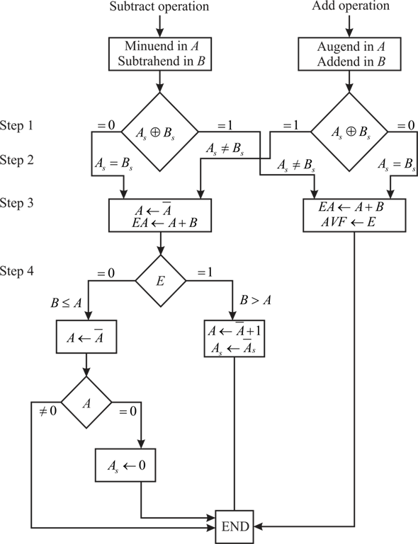
What is Binary Adder-Subtractor in Computer Architecture? Computer Architecture Computer Science Network The subtraction of binary numbers can be completed effectively by creating the 2's complement of addend bits and inserting it to the augend bits.

4 bit binary adder circuit 4 bit binary addition F88 F99
Courses Prerequisite - Full adder, Full Subtractor Parallel Adder - A single full adder performs the addition of two one bit numbers and an input carry. But a Parallel Adder is a digital circuit capable of finding the arithmetic sum of two binary numbers that is greater than one bit in length by operating on corresponding pairs of bits in parallel.
Full Adder Circuit Diagram Using Multiplexer
A Binary Adder is a digital circuit that implements the arithmetic sum of two binary numbers supported with any length is known as a binary adder. It is generated using full-adder circuits connected in sequence. The output carries from one full-adder linked to the input carry of the next full-adder.
Fixed Point Arithmetic Addition and Subtraction Computer Architecture
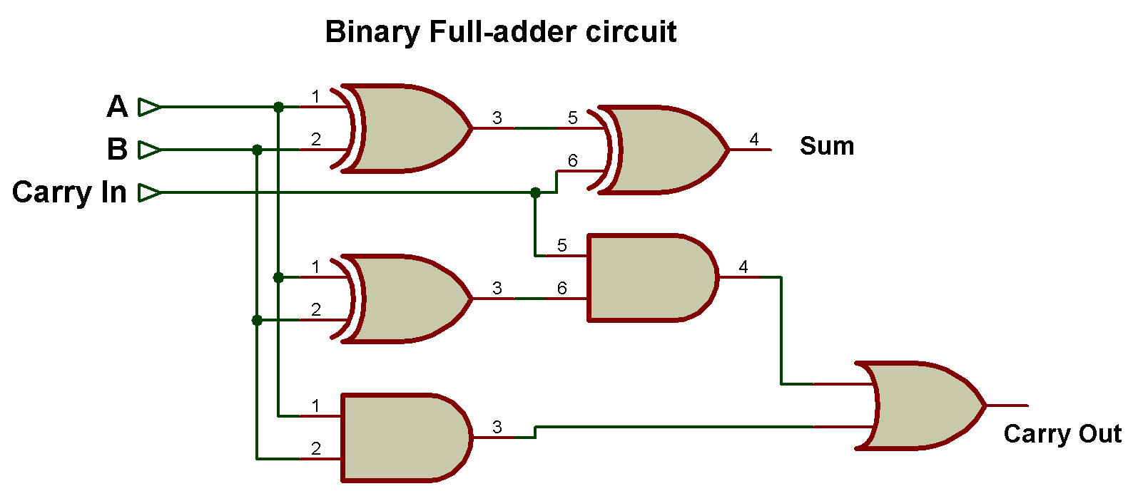
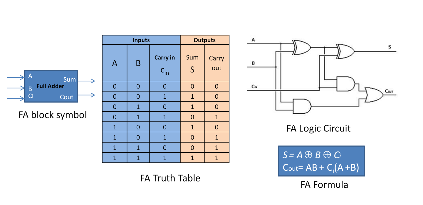
A basic Binary Adder circuit can be made from standard AND and Ex-OR gates allowing us to "add" together two single bit binary numbers, A and B. The addition of these two digits produces an output called the SUM of the addition and a second output called the CARRY or Carry-out, ( C OUT ) bit according to the rules for binary addition.

FULL ADDER "ELECTRONIC WORKBENCH" CIRCUIT DIAGRAM BINARY ADDER YouTube
A binary adder is a digital logic circuit that is used to perform the arithmetic sum of two binary numbers. A binary adder is implemented by combining logic gates in a proper manner. Binary adder performs the addition operation on two binary numbers as per the following four rules: 0 + 0 = 0. 0 + 1 = 1. 1 + 0 = 1.

Binary Logic
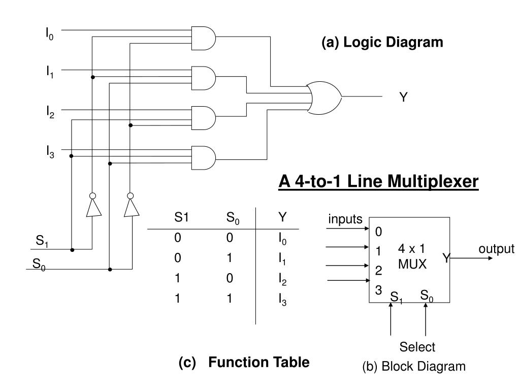
1. Arithmetic: Adders Subtractors Multipliers Comparators 2. Data Handling: Multiplexers DeMultiplexers Encoders and Decoders 3. Code Converters: BCD to Excess-3 code and vice versa BCD to Gray code and vice versa Seven Segment Design of Half Adders and Full Adders: